
Page 405 - ISCAR(HOLE_MAKING_CATALOG_65)
P. 405
USER GUIDE
ITS BORE
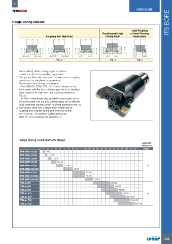
Rough Boring Options
Light Roughing
Roughing with High or Semi-Finishing
Roughing with High Feed Cutting Depth Applications
Ø Ø Ø Ø Ø
A A A A A A A1 A
CR LNHT CR LNHT CR SOMT CR SOMT IHSR IHSR IHCR IHSR PLT IHSR
Fig. a Fig. b Fig. c
1 Radial setting of the cutting edges should be
carried out with tool presetting equipment.
2 Boring bars fitted with two insert pockets are for roughing
operations involving heavy chip removal.
The double-insert boring bars include:
- Two IHSR/CR SOMT/CR LNHT insert holders on the
same plane with the two cutting edges set at an identical
radial distance for high feed rate roughing operations
(Fig. a).
- An IHCR insert holder and an IHSR insert holder not on
the same plane with the two cutting edges set at different
radial distances for high-depth roughing operations (Fig. b).
3 Boring bars fitted with a single insert holder are for
roughing and finishing operations involving normal
chip removal. The serrated surface protection
plate PLT should always be used (Fig. c).
Rough Boring Head Diameter Range
Assembly
Reference
10 20 30 40 50 60 70 80 90 100 110 120 130 200 300 400 500 600 700 800 900 1000 1100 1200 Page
BHR MB16-16x34 18-22
BHR MB20-20x40 22-28
BHR MB25-25x50 28-38
BHR MB32-32x63 35.5-50
BHR MB40-40x80 50-68 843
BHR MB50-50x100 68-90
BHR MB50-63x80 90-120
BHR MB63-63x125 90-120
BHR MB80-80x140 120-200
TCH AL200 200-602
TCH AL300 300-702
TCH AL400 400-802
TCH AL 500 500-902 847
TCH AL 600 600-1002
TCH AL 700 700-1102
TCH AL 800 800-1202
403