
Page 124 - ISCAR(HOLE_MAKING_CATALOG_65)
P. 124
USER GUIDE
INDEXABLE DRILLS
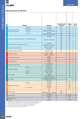
Machining Data for DR Drills
ISO
2
(1)
Condition
[N/mm ]
No.
HB
< 0.25 %C
420
1
Annealed
125
Annealed
190
650
≥ 0.25 %C
2
Non-alloy steel and cast Material Quenched and tempered Tensile Strength Hardness Group
250
< 0.55 %C
850
3
steel, free cutting steel
Annealed 750 220 4
≥ 0.55 %C
Quenched and tempered 1000 300 5
Annealed 600 200 6
P 930 275 7
Low alloy and cast steel (less than 5% of alloying elements)
Quenched and tempered 1000 300 8
1200 350 9
Annealed 680 200 10
High alloyed steel, cast steel and tool steel
Quenched and tempered 1100 325 11
Ferritic/martensitic 680 200 12
Stainless steel and cast steel
Martensitic 820 240 13
M Stainless steel and cast steel Austenitic, duplex 600 180 14
Ferritic / pearlitic 180 15
Gray cast iron (GG)
Pearlitic / martensitic 260 16
Ferritic 160 17
K Nodular cast iron (GGG)
Pearlitic 250 18
Ferritic 130 19
Malleable cast iron
Pearlitic 230 20
Not hardenable 60 21
Aluminum-wrought alloys
Hardenable 100 22
≤12% Si Not hardenable 75 23
Aluminum-cast alloys Hardenable 90 24
>12% Si High temperature 130 25
N
>1% Pb Free cutting 110 26
Copper alloys Brass 90 27
Electrolytic copper 100 28
Duroplastics, fiber plastics 29
Non metallic
Hard rubber 30
Annealed 200 31
Fe based
Hardened 280 32
High temperature alloys Annealed 250 33
S Ni or Co based Hardened 350 34
Cast 320 35
Pure 400 36
Titanium alloys
Alpha+beta alloys, hardened 1050 37
Hardened 55 HRC 38
Hardened steel
H Hardened 60 HRC 39
Chilled cast iron Cast 400 40
Cast iron Hardened 55 HRC 41
• This table refers to 2/3xD drill ratio usage. For 4xD ratio decrease cutting data by 15%
• Chipformer should be selected based on our geometry range recommendations
• When using external coolant supply only, reduce cutting speed by 10%
• Use internal coolant supply when machining austenitic stainless steel
(1) For workpiece materials list, see pages 495-524
122 ISCAR