
Page 120 - ISCAR(HOLE_MAKING_CATALOG_65)
P. 120
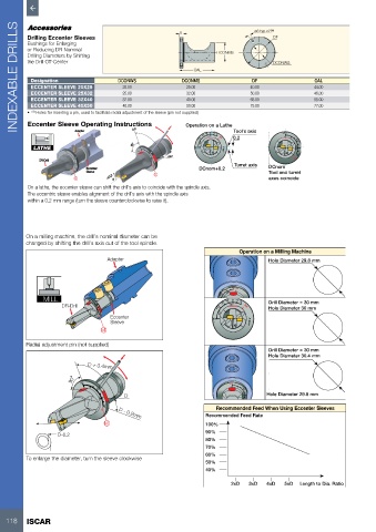
INDEXABLE DRILLS  Drilling Eccenter Sleeves  DCONWS  5 DCONMS   DCONMS    40.00  DCONWS        OAL
                                                                                  ø3 typ.x2 (1)

                                                                                        DF
          Bushings for Enlarging
          or Reducing DR Nominal
          Drilling Diameters by Shifting
          the Drill Off-Center
                                                              OAL
           Designation
                                                                                 DF
                                                            25.00
                                                                                                     44.00
           ECCENTER SLEEVE 20X25
                                        20.00
                                                            32.00
           ECCENTER SLEEVE 25X32
                                                                                                     46.00
                                        25.00
                                                                                50.00
                                                                                65.00
                                                                                                     55.00
                                                            40.00
           ECCENTER SLEEVE 32X40
                                        32.00
           ECCENTER SLEEVE 40X50
                                        40.00
                                                                                75.00
                                                                                                     77.00
                                                            50.00
          •  (1)  Holes for inserting a pin, used to facilitate radial adjustment of the sleeve (pin not supplied)
          Eccenter Sleeve Operating Instructions
                                                            Operation on a Lathe
                                           0.0

                                                                           Tool’s axis
                         Adapter
                                                                +12 +8 +4  +8 0 -4 -8 L M  0.2  +0.4 0  +0.2
            LATHE                          90  +0.4            +16  +4  0                      +0.2  0
                                              0  +0.2                   X.001”
                                                      +0.2                                    L  -0.2 M
             DR-Drill                            +0.2 0
                                                                           Turret axis
                            Eccenter                            DCnom+0.2             DCnom
                                                  -0.2 M
                                                 L
                            Sleeve                L                                   Tool and turret
                        L
                         L         +0.2  0                                            axes coincide
          On a lathe, the eccenter sleeve can shift the drill’s axis to coincide with the spindle axis.
          The eccentric sleeve enables alignment of the drill’s axis with the spindle axis
          within a 0.2 mm range (turn the sleeve counterclockwise to raise it).

         On a milling machine, the drill’s nominal diameter can be
         changed by shifting the drill’s axis out of the tool spindle.
                                                                             Operation on a Milling Machine
                                   Adapter                                            Hole Diameter 29.8 mm
                                                                          -0.2 M
                                                                         0 +0.2  L
               MILL          +0.4                                      +0.2
                             0                                          +0.4 +8 +4  0 -4  -8  Drill Diameter = 30 mm
                     DR-Drill  +0.2  +0.2  0                          +12  +8  L M    Hole Diameter 30 mm
                                    Eccenter                           +4  0
                                L
                                -0.2 M
                                    Sleeve                           +16        X.001”
                                 M
         Radial adjustment pin (not supplied)
                                                                                      Drill Diameter = 30 mm
                                                                                      Hole Diameter 30.4 mm
                             D + 0.4mm
                        90  +0.4                                          +0.4
                            0  +0.2                                       0   +0.2
                                         D                                    +0.2  0  Hole Diameter 29.8 mm
                                  0
                                +0.2
                                                                             L
                                                                     Recommended Feed When Using Eccenter Sleeves
                                                                               -0.2 M
                                  -0.2 L M
                                                                  Recommended Feed Rate
                                       D - 0.2mm
                                  M                               100%
                                                                  90%
                   D-0.2
                                                                  80%
                                                                  70%
          D+0.4                                                   60%
         To enlarge the diameter, turn the sleeve clockwise
                                                                  50%
                                                                  40%
                                                                          2xD   3xD  4xD   5xD  Length to Dia. Ratio


   118    ISCAR