Page 257 - ISCAR(MILLINGCATALOG 38_2021)
P. 257

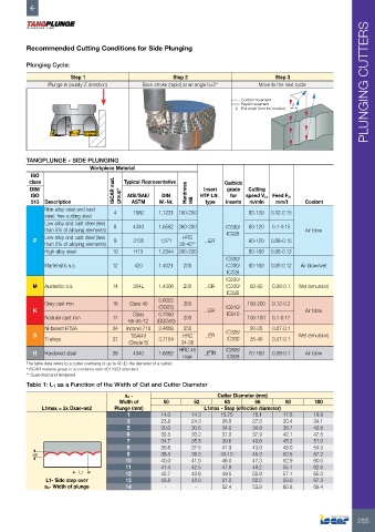
Recommended Cutting Conditions for Side Plunging

         Plunging Cycle:

                        Step 1                          Step 2                          Step 3
                Plunge in (axially-Z direction)  Back stroke (rapid) at an angle b≥2°  Move to the next cycle         PLUNGING CUTTERS

                                                                              Control movement
                                                                              Rapid movement  β
                                                                            β - Exit angle from the material


         TANGPLUNGE - SIDE PLUNGING
                              Workpiece Material
           ISO
          class                         Typical Representative          Carbide
           DIN/                      ISCAR mat.             Hardness   Insert   grade   Cutting
           ISO                         group*  AISI/SAE/  DIN   HTP LN…   for   speed Vc,  Feed Fz,
           513  Description                ASTM     W.-Nr.    HB  type   inserts  m/min  mm/t     Coolant
               Non-alloy steel and cast   4  1060  1.1221 180-200               80-130  0.12-0.15
               steel, free cutting steel
               Low alloy and cast steel (less   8  4340  1.6582 260-300         80-120  0.1-0.15
               than 5% of alloying elements)                             IC830/                   Air blow
                                                                         IC928
               Low alloy and cast steel (less              HRC
            P                        9     3135     1.571         …ER           80-120  0.08-0.15
               than 5% of alloying elements)              35-40**
               High alloy steel      10     H13    1.2344 200-220               80-100  0.08-0.12
                                                                         IC830/
               Martensitic s.s.      12     420    1.4021  200           IC330/  80-100  0.08-0.12  Air blow/wet
                                                                         IC328
                                                                         IC830/
           M   Austenitic s.s.       14    304L    1.4306  200    …ER    IC330/  60-80  0.08-0.1  Wet (emulsion)
                                                                         IC328
                                                   0.6025
               Grey cast iron        16   Class 40  (GG25)   250                150-200  0.12-0.2
            K                                                     …ER    IC810/                   Air blow
                                                                         IC910
               Nodular cast iron     17    Class   0.7050   200                 100-180  0.1-0.17
                                          65-45-12  (GGG50)
               Ni-based HTSA         34  Inconel 718  2.4668  350               20-25   0.07-0.1
            S                              Ti6Al4V         HRC    …ER    IC328/                 Wet (emulsion)
               Ti alloys             37            3.7164                IC330  35-40   0.07-0.1
                                          (Grade 5)        34-36
                                                          HRC 45         IC808/
            H  Hardened steel        38    4340    1.6582         …ETR          70-100  0.08-0.1  Air blow
                                                           max           IC908
         The table data refers to a cutter overhang of up to 4D (D-the diameter of a cutter)
         * ISCAR material group in accordance with VDI 3323 standard
         ** Quenched and tempered
         Table 1: L1 as a Function of the Width of Cut and Cutter Diameter

                                         ae -                         Cutter Diameter (mm)
                                       Width of      50        52       63        66        80       100
              L1max = 2x Dxae-ae2    Plunge (mm)                  L1max - Step (effective diameter)
                                         1          14.0      14.3     15.75     16.1      17.8      19.9
                                         3          23.8      24.3      26.8     27.5      30.4      34.1
                                         5          30.0      30.6      34.0     34.9      38.7      43.6
                                         6          32.5      33.2      37.0     37.9      42.1      47.5
                                         7          34.7      35.5      39.6     40.6      45.2      51.0
                                         8          36.6      37.5      41.9     43.0      48.0      54.3
           ae                            9          38.5      39.3     43.10     45.3      50.5      57.2
                                         10         40.0      41.0      46.0     47.3      52.9      60.0
                                         11         41.4      42.5      47.8     49.2      55.1      62.6
                          L1             12         42.7      43.8      49.5     50.9      57.1      65.0
                L1- Side step over       13         43.8      45.0      51.0     52.5      59.0      67.3
               ae- Width of plunge       14          -         -        52.4     53.9      60.8      69.4


                                                                                                                   255
   252   253   254   255   256   257   258   259   260   261   262