
Page 343 - ISCAR(TURNING-CATALOG-42-2022)
P. 343
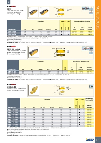
GEMI                                                  ±0.08  10 Ref.    2.9 Ref.
          Utility Double-Ended Inserts                              8°
            for Internal and External
          Grooving and Turning                                    CW
                                                                      RE  BW                                          GROOVE-TURN


                                             Dimensions                  Tough 1   Hard  Recommended  Machining Data


                                                                          IC808  IC908  IC807  ap  f turn  f groove
           Designation        CW       RE     CWTOL (1)  RETOL (2)  BW                 (mm)    (mm/rev)  (mm/rev)
           GEMI 2002N         2.00     0.20     0.02     0.050    1.60   •            0.25-0.80  0.05-0.10  0.04-0.08
           GEMI 3002M         3.00     0.20     0.02     0.050    2.20   •   •        0.25-1.30  0.10-0.14  0.05-0.09
           GEMI 3002N         3.00     0.20     0.02     0.050    2.20   •        •   0.25-1.00  0.07-0.12  0.04-0.08
          •  GEMI N inserts for ductile materials and low feed   •  DMIN for internal application=11.5 mm
          •  For cutting speed recommendations and user guide, see pages 419-428, 432-436
          (1)  Cutting width tolerance (+/-)
          (2)  Corner radius tolerance (+/-)
          For tools, see pages: AVC-GEAIR/L (346) • E-GEHIR / E-GHIR (340) • GEAIR/L (340) • GEHIR/L (338) • GEHIR/L-SC (339) • GEHSR (373) • GEHSR/L-SL (372)


          GEMI (full radius)                                  ±0.08    10 Ref.
          Utility Double-Ended Full Radius
          Inserts for Internal and External                       8°
          Grooving and Profiling
                                                                CW
                                                                  RE     BW

                                             Dimensions                                Recommended  Machining Data


                                                                              IC808  ap        f turn   f groove
           Designation     CW         RE      CWTOL (1)  RETOL (2)  BW               (mm)     (mm/rev)  (mm/rev)
           GEMI 2010Y      2.00       1.00      0.02      0.050     1.60     •      0.10-1.00  0.06-0.12  0.03-0.08
           GEMI 3015Y      3.00       1.50      0.04      0.050     2.20     •      0.10-1.50  0.10-0.18  0.05-0.10
          •  DMIN for internal application=11.5 mm   •  For cutting speed recommendations and user guide, see pages 419-428, 432-436
          (1)  Cutting width tolerance (+/-)
          (2)  Corner radius tolerance (+/-)
          For tools, see pages: AVC-GEAIR/L (346) • E-GEHIR / E-GHIR (340) • GEAIR/L (340) • GEHIR/L (338) • GEHIR/L-SC (339) • GEHSR (373) • GEHSR/L-SL (372)


          GEPI (W<M)                                             ±0.025  10 Ref.
          Precision Ground Double-Ended                              8°          2.9 Ref.
          Inserts for Internal Grooving                             RE    BW
                                                                CW
                                                                         CDX

                                                                                                      Recommended
                                                     Dimensions                           Tough 1   Hard
                                                                                                      Machining Data

                                                                                           IC528  IC08  IC908  f groove
           Designation       CW         RE       CWTOL (1)  RETOL (2)  CDX (3)    BW                     (mm/rev)
           GEPI 1.00-0.10    1.00       0.10       0.00      0.030      1.60      1.80    •   •   •     0.01-0.03
           GEPI 1.00-0.50    1.00       0.50       0.00      0.030      1.60      1.80            •     0.01-0.04
           GEPI 1.04-0.00    1.04       0.00       0.00      0.030      1.60      1.80    •   •   •     0.01-0.03
           GEPI 1.20-0.00    1.20       0.00       0.00      0.030      1.80      1.80    •   •   •     0.01-0.03
           GEPI 1.25-0.10    1.25       0.10       0.00      0.030      2.00      1.80    •   •   •     0.02-0.04
           GEPI 1.40-0.00    1.40       0.00       0.00      0.030      2.00      1.80    •   •   •     0.02-0.04
           GEPI 1.47-0.00    1.47       0.00       0.00      0.030      2.00      1.80    •   •   •     0.02-0.04
           GEPI 1.50-0.10    1.50       0.10       0.00      0.030      2.00      1.80    •   •   •     0.02-0.04
           GEPI 1.57-0.15    1.57       0.15       0.00      0.030      2.00      1.80    •   •   •     0.02-0.05
           GEPI 1.70-0.05    1.70       0.05       0.02      0.030      2.50      1.80    •   •   •     0.02-0.05
           GEPI 1.78-0.15    1.78       0.15       0.02      0.030      2.50      1.80    •   •   •     0.02-0.05
          •  Toolholder seat needs to be modified according to insert profile to ensure clearance   •  DMIN for internal application=11.5mm
          •  For cutting speed recommendations and user guide, see pages 419-428, 432-436
          (1)  Cutting width tolerance (+/-)
          (2)  Corner radius tolerance (+/-)
          (3)  Cutting depth maximum
          For tools, see pages: E-GEHIR / E-GHIR (340) • GEHIMR/L (337) • GEHIMR/L-SC (337) • GEHSR (373) • GEHSR/L-SL (372)


                                                                                                                   341