
Page 299 - ISCAR(HOLE_MAKING_CATALOG_65)
P. 299
USER GUIDE
GUNDRILLS
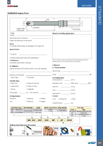
SUMOGUN Inquiry Form
Tube L1
Dk7 Th
Connector T
SUMOCHAM GDV Driver
Drilling Head L
1. Tool Sketch of drilling application
Quantity
Nominal diameter and tolerance
Please fill in dimensions on the sketch.
Driver
For standard drivers please use designation from page 294
Special Driver
o Code No.
o Special, please attach sketch and specifications.
2. Workpiece Note: It may be necessary to change several of the parameters that you
indicated, based on our experience with your application.
(If possible, please attach a drawing)
3. Machine
2.1 Material
3.1 Technical Data
Material description (DIN material number or any other standard):
Machine Type
Hardness and Properties: Power: kW
o Short Chips o Long Chips 3.2 Cutting Data:
Cutting Speed Vc m/min
2.2 Hole Type
o Blind Hole o Drilling into Pre-hole Revolutions Nmin RPM, Nmax RPM
o Angled Entry o Drilling into Solid Feed Fmin mm/rev,
o Boring o Angled Exit
Fmax mm/rev
Drilling Depth mm Hole Tolerance
Feed Rate VF mm/min
2.3 Application: Coolant:
Workpiece: o Stationary o Rotating o Oil o Soluble Oil o Other
Tool: o Stationary o Rotating
Coolant Pressure: Bar
Drill Body Type Hole Diameter Length Metric Fine Pictch Dwg. Number Tool Type
SNT Steel body 1=M16 Code Type
CNT For C.N.C Ø10.00-25.99 Drilling Depth 1=M20 4 last digits No code Standard shape and size
GDT For Gundrill Total length GP Guide Pads
SC Special Connector
PT P-Tube
MN ### - XXX - XXX - MF 1 GP - XXXX
Drilling Head Mounting Procedure
1 2 3 4 5
297