
Page 301 - ISCAR(TURNING-CATALOG-42-2022)
P. 301
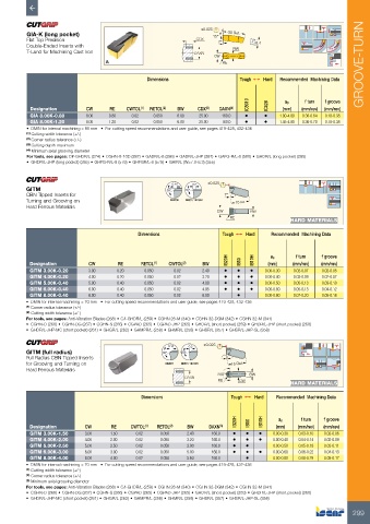
GIA-K (long pocket)                                     ±0.025 15°  30   Ref.
          Flat Top Precision                                    CDX    7°          6.4
          Double-Ended Inserts with                                         BW
          T-Land for Machining Cast Iron                        DAXN
                                                                      CW
                                                                         RE                                           GROOVE-TURN

                                                Dimensions                    Tough 1   Hard  Recommended  Machining Data


                                                                                 IC5010  IC428  ap  f turn  f groove
           Designation       CW     RE    CWTOL (1)  RETOL (2)  BW  CDX (3)  DAXN (4)       (mm)  (mm/rev)  (mm/rev)
           GIA 8.00K-0.80    8.00   0.80   0.02   0.050   6.00   25.00  160.0   •     •    1.00-4.80  0.36-0.64  0.18-0.38
           GIA 8.00K-1.20    8.00   1.20   0.02   0.050   6.00   25.00  160.0   •     •    1.45-4.80  0.36-0.70  0.18-0.38
          •  DMIN for internal machining = 65 mm   •  For cutting speed recommendations and user guide, see pages 419-428, 432-436
          (1)  Cutting width tolerance (+/-)
          (2)  Corner radius tolerance (+/-)
          (3)  Cutting depth maximum
          (4)  Minimum axial grooving diameter
          For tools, see pages: C#-GHDR/L (274) • CGHN-8-10D (287) • GADR/L-8 (286) • GADR/L-JHP (287) • GAFG-R/L-8 (580) • GHDR/L (long pocket) (285)
          •  GHDR/L-JHP (long pocket) (285) • GHFG-R/L-8 (579) • GHFGR/L-8 (579) • GHIR/L (W=7.0-8.3) (355)

                                                                    ±0.025
         GITM                                          30°  0.15  20°  0.2
         CBN Tipped Inserts for                                          7°
         Turning and Grooving on                        IB20H  IB50 / IB10H  15 Ref.
         Hard Ferrous Materials
                                                                       CW         BW
                                                                           RE
                                                                                              HARD MATERIALS
                                             Dimensions                  Tough 1   Hard  Recommended  Machining Data


                                                                          IB20H    IB10H  ap    f turn   f groove
           Designation        CW       RE     RETOL (1)  CWTOL (2)  BW        IB50     (mm)    (mm/rev)  (mm/rev)
           GITM 3.00K-0.20    3.00     0.20     0.050    0.02     2.40   •   •    •   0.00-0.30  0.02-0.07  0.02-0.05
           GITM 4.00K-0.20    4.00     0.20     0.050    0.02     3.20   •   •    •   0.00-0.40  0.03-0.09  0.02-0.07
           GITM 5.00K-0.40    5.00     0.40     0.050    0.02     4.00   •   •    •   0.00-0.50  0.05-0.13  0.03-0.10
           GITM 6.00K-0.40    6.00     0.40     0.050    0.02     4.95   •   •    •   0.00-0.60  0.05-0.15  0.04-0.12
           GITM 8.00K-0.40    8.00     0.40     0.050    0.02     6.00       •        0.00-0.80  0.07-0.20  0.05-0.16
         •  DMIN for internal machining = 70 mm   •  For cutting speed recommendations and user guide, see pages 419-428, 432-436
         (1)  Corner radius tolerance (+/-)
         (2)  Cutting width tolerance (+/-)
         For tools, see pages: Anti-Vibration Blades (268) • C#-GHDR/L (259) • CGHN 26-M (340) • CGHN 32-DGM (342) • CGHN 32-M (341)
         •  CGHN-D (266) • CGHN-DG (267) • CGHN-S (266) • CGPAD (265) • CGPAD-JHP (265) • GHDR/L (short pocket) (259) • GHDR/L-JHP (short pocket) (260)
         •  GHDR/L-JHP-MC (short pocket) (261) • GHGR/L (262) • GHMPR/L (258) • GHMR/L (258) • GHSR/L (357) • GHSR/L-JHP-SL (358)
                                                       0.15   0.2  ±0.025

         GITM (full radius)                          30°   20°
         Full Radius CBN Tipped Inserts                                 7°
         for Grooving and Turning on                  IB20H  IB50 / IB10H  15 Ref.
         Hard Ferrous Materials
                                                                       200°      BW
                                                            DAXN
                                                                       RE     CW
                                                                                              HARD MATERIALS
                                               Dimensions                  Tough 1   Hard  Recommended  Machining Data


                                                                             IB20H  IB50  IB10H  ap  f turn  f groove
           Designation      CW       RE    CWTOL (1)  RETOL (2)  BW  DAXN (3)             (mm)   (mm/rev)  (mm/rev)
           GITM 3.00K-1.50  3.00     1.50    0.02    0.050   2.40    160.0  •   •   •    0.00-0.30  0.03-0.10  0.02-0.06
           GITM 4.00K-2.00  4.00     2.00    0.02    0.050   3.20    160.0  •   •   •    0.00-0.40  0.04-0.14  0.02-0.09
           GITM 5.00K-2.50  5.00     2.50    0.02    0.050   3.90    160.0  •   •        0.00-0.50  0.05-0.18  0.03-0.11
           GITM 6.00K-3.00  6.00     3.00    0.02    0.050   5.00    160.0  •   •   •    0.00-0.60  0.06-0.22  0.04-0.13
           GITM 8.00K-4.00  8.00     4.00    0.02    0.050   5.60    160.0      •        0.00-0.80  0.08-0.29  0.05-0.17
         •  DMIN for internal machining = 70 mm   •  For cutting speed recommendations and user guide, see pages 419-428, 432-436
         (1)  Cutting width tolerance (+/-)
         (2)  Corner radius tolerance (+/-)
         (3)  Minimum axial grooving diameter
         For tools, see pages: Anti-Vibration Blades (268) • C#-GHDR/L (259) • CGHN 26-M (340) • CGHN 32-DGM (342) • CGHN 32-M (341)
         •  CGHN-D (266) • CGHN-DG (267) • CGHN-S (266) • CGPAD (265) • CGPAD-JHP (265) • GHDR/L (short pocket) (259) • GHDR/L-JHP (short pocket) (260)
         •  GHDR/L-JHP-MC (short pocket) (261) • GHGR/L (262) • GHMPR/L (258) • GHMR/L (258) • GHSR/L (357) • GHSR/L-JHP-SL (358)

                                                                                                                   299