
Page 37 - ISCAR(MILLINGCATALOG 38_2021)
P. 37
Rd°
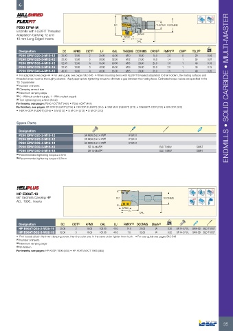
P290 EPW-M DC THSZMS DCONMS
Endmills with FLEXFIT Threaded
Adaptation Carrying 12 and APMX DRVS
18 mm Long Edged Inserts LF
OAL
Designation DC APMX CICT (1) LF OAL THSZMS DCONMS DRVS (2) RMPX° (3) CSP (4) TQ_3 (5) kg
P290 EPW D20-2-M10-12 20.00 12.00 2 25.00 45.00 M10 18.00 15.0 2.0 0 29 0.04
P290 EPW D25-3-M12-12 25.00 12.00 3 30.00 52.00 M12 21.00 19.0 1.4 1 33 0.07
P290 EPW D32-4-M16-12 32.00 12.00 4 35.00 60.00 M16 29.00 25.0 1.0 1 40 0.16
P290 EPW D32-3-M16-18 32.00 18.00 3 40.00 65.00 M16 29.00 25.0 2.0 1 40 0.15
P290 EPW D40-4-M16-18 40.00 18.00 4 40.00 65.00 M16 29.00 25.0 1.5 1 40 0.20
• For adaptation see page 44 • For user guide, see pages 542-548 • When mounting items with FLEXFIT threaded adaptation to their holders, the mating surfaces and
threaded areas must be thoroughly cleaned. Apply appropriate tightening torque to eliminate a gap between the mating faces. Estimated torque values are specified in the
TQ_3 parameter
(1) Number of inserts
(2) Clamping wrench size ENDMILLS • SOLID CARBIDE • MULTI-MASTER
(3) Maximum ramping angle
(4) 0 - Without coolant supply, 1 - With coolant supply
(5) Tool tightening torque Nxm (lbfxin)
For inserts, see pages: P290 ACCT/KT (461) • P290 ACKT (461)
For holders, see pages: BT-ODP (FLEXFIT) (314) • C#-ODP (FLEXFIT) (314) • CAB M-M (FLEXFIT) (312) • DIN69871-ODP (315) • ER-ODP (315)
• HSK A-ODP (FLEXFIT) (316) • S M (312) • S M-C-H (312) • S M-CF (313)
Spare Parts
Designation
P290 EPW D20-2-M10-12 SR M3X0.5-L7.4 IP9 (b) IP-9/151
P290 EPW D25-3-M12-12 SR M3X0.5-L7.4 IP9 (b) IP-9/151
P290 EPW D32-4-M16-12 SR M3X0.5-L7.4 IP9 (b) IP-9/151
P290 EPW D32-3-M16-18 SR 14-544/S (a) BLD T15/M7 SW6-T
P290 EPW D40-4-M16-18 SR 14-544/S (a) BLD T15/M7 SW6-T
(a) Recommended tightening torque:2.0 N*m
(b) Recommended tightening torque:4.8 Nxm
Rd°
HP E90AT-19
90° Endmills Carrying HP DC DCONMS
AD.. 1906.. Inserts
APMX
LU
OAL
Designation DC CICT (1) APMX OAL LU RMPX° (2) DCONMS Shank (3) kg
HP E90AT-D25-2-W25-19 25.00 2 18.00 100.00 40.0 14.0 25.00 W 0.30 SR 14-571/L SW6-SD BLD T10/S7
HP E90AT-D32-3-W32-19 32.00 3 18.00 105.00 40.0 7.0 32.00 W 0.52 SR 14-571/L SW6-SD BLD T10/S7
• First loosely attach the inner clamping screw, then the outer one. In the same order tighten them both. • For user guide see pages 542-548
(1) Number of inserts
(2) Maximum ramping angle
(3) W-Weldon
For inserts, see pages: HP ADCR 1906 (464) • HP ADKT/ADCT 1906 (464)
35