
Page 375 - ISCAR(TURNING-CATALOG-42-2022)
P. 375
OAL
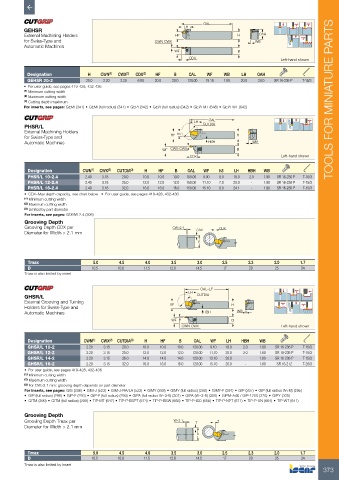
GEHSR LH
External Machining Holders HF H OAH
for Swiss-Type and CWN-CWX WB
Automatic Machines
WF B
CDX Left-hand shown
Designation H CWN (1) CWX (2) CDX (3) HF B OAL WF WB LH OAH
GEHSR 20-2 20.0 2.20 3.20 6.80 20.0 20.0 120.00 19.10 1.80 20.0 24.0 SR 16-236 P T-15/3
• For user guide, see pages 419-428, 432-436
(1) Minimum cutting width
(2) Maximum cutting width
(3) Cutting depth maximum TOOLS FOR MINIATURE PARTS
For inserts, see pages: GEMI (341) • GEMI (full radius) (341) • GEPI (342) • GEPI (full radius) (342) • GEPI-MT (648) • GEPI-WT (642)
OAL
PHSR/L LH CUTDIA
External Machining Holders
for Swiss-Type and HF h3 H
Automatic Machines HBH WB
WF CWX-CWX B
CDX Left-hand shown
Designation CWN (1) CWX (2) CUTDIA (3) H HF B OAL WF h3 LH HBH WB
PHSR/L 10-2.4 2.40 3.18 20.0 10.0 10.0 10.0 150.00 9.00 8.0 18.0 2.0 1.90 SR 16-236 P T-15/3
PHSR/L 12-2.4 2.40 3.18 25.0 12.0 12.0 12.0 150.00 11.10 7.0 20.0 - 1.90 SR 16-236 P T-15/3
PHSR/L 16-2.4 2.40 3.18 32.0 16.0 16.0 16.0 150.00 15.10 8.0 24.1 - 1.90 SR 16-236 P T-15/3
• CDX=Max depth capacity, see chart below • For user guide, see pages 419-428, 432-436
(1) Minimum cutting width
(2) Maximum cutting width
(3) Limited by part diameter
For inserts, see pages: GDMW 2.4 (306)
Grooving Depth
Grooving Depth CDX per CW>2.1 CDX CDX
Diameter for Width > 2.1 mm
D
Tmax 5.0 4.5 4.0 3.5 3.0 2.5 2.3 2.0 1.7
D 10.5 10.8 11.5 12.6 14.5 17 20 25 34
Tmax is also limited by insert
OAL=LF
GHSR/L LH CUTDIA
External Grooving and Turning HF H
Holders for Swiss-Type and
Automatic Machines HBH WB
WF B
CWN-CWX Left-hand shown
Designation CWN (1) CWX (2) CUTDIA (3) H HF B OAL WF LH HBH WB
GHSR/L 10-2 2.20 3.15 20.0 10.0 10.0 10.0 120.00 9.10 18.0 2.0 1.80 SR 16-236 P T-15/3
GHSR/L 12-2 2.20 3.15 25.0 12.0 12.0 12.0 120.00 11.10 20.0 2.0 1.80 SR 16-236 P T-15/3
GHSR/L 14-2 2.20 3.15 26.0 14.0 14.0 14.0 120.00 13.10 20.0 - 1.80 SR 16-236 P T-15/3
GHSR/L 16-2 2.20 3.15 32.0 16.0 16.0 16.0 120.00 15.10 26.0 - 1.80 SR 16-212 T-20/3
• For user guide, see pages 419-428, 432-436
(1) Minimum cutting width
(2) Maximum cutting width
(3) For CW>2.1 mm: grooving depth depends on part diameter
For inserts, see pages: GIG (296) • GIM-J (522) • GIM-J-RA/LA (522) • GIMY (288) • GIMY (full radius) (290) • GIMY-F (291) • GIP (297) • GIP (full radius W<M) (295)
• GIP (full radius) (296) • GIP-E (293) • GIP-E (full radius) (294) • GIPA (full radius W=3-6) (301) • GIPA (W=3-6) (300) • GIPM-A46 / GIP-1250 (375) • GIPY (300)
• GITM (299) • GITM (full radius) (299) • TIP-MT (647) • TIP-P-BSPT (674) • TIP-P-BSW (668) • TIP-P-ISO (658) • TIP-P-NPT (671) • TIP-P-UN (664) • TIP-WT (641)
Grooving Depth
Grooving Depth Tmax per W>2.1 T T
Diameter for Width > 2.1 mm
D
Tmax 5.0 4.5 4.0 3.5 3.0 2.5 2.3 2.0 1.7
D 10.5 10.8 11.5 12.6 14.5 17 20 25 34
Tmax is also limited by insert
373