
Page 575 - ISCAR(TURNING-CATALOG-42-2022)
P. 575
WF
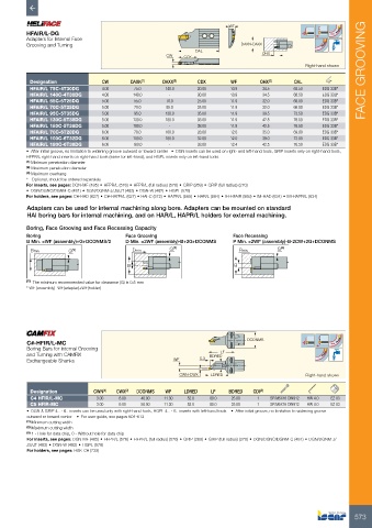
HFAIR/L-DG
Adapters for Internal Face
Grooving and Turning DAXN-DAXX
OAL
CW CDX OHX
Right-hand shown FACE GROOVING
Designation CW DAXN (1) DAXX (2) CDX WF OHX (3) OAL
HFAIR/L 75C-4T30DG 4.00 75.0 140.0 30.00 10.9 34.5 68.50 EDG 33B*
HFAIR/L 140C-4T30DG 4.00 140.0 - 30.00 10.9 34.5 68.50 EDG 33B*
HFAIR/L 55C-5T25DG 5.00 55.0 70.0 25.00 11.9 32.0 66.00 EDG 33B*
HFAIR/L 70C-5T25DG 5.00 70.0 95.0 25.00 11.9 32.0 66.00 EDG 33B*
HFAIR/L 95C-5T35DG 5.00 95.0 130.0 35.00 11.9 39.5 73.50 EDG 33B*
HFAIR/L 130C-5T38DG 5.00 130.0 180.0 38.00 11.9 42.5 76.50 EDG 33B*
HFAIR/L 180C-5T38DG 5.00 180.0 - 38.00 11.9 42.5 76.50 EDG 33B*
HFAIR/L 70C-6T28DG 6.00 70.0 100.0 28.00 12.0 35.0 69.00 EDG 33B*
HFAIR/L 100C-6T32DG 6.00 100.0 180.0 32.00 12.0 39.0 73.00 EDG 33B*
HFAIR/L 180C-6T38DG 6.00 180.0 - 38.00 12.4 42.5 76.50 EDG 33B*
• After initial groove, no limitation to widening groove outward or toward center • DGN inserts can be used on right- and left-hand tools, GRIP inserts only on right-hand tools,
HFPR/L right-hand inserts on right-hand tools (same for left-hand), and HGPL inserts only on left-hand tools.
(1) Minimum penetration diameter
(2) Maximum penetration diameter
(3) Maximum overhang
* Optional, should be ordered separately
For inserts, see pages: DGN-MF (485) • HFPR/L (576) • HFPR/L (full radius) (576) • GRIP (269) • GRIP (full radius) (270)
• DGN/DGNC/DGNM-C (481) • DGN/DGNM-J/JS/JT (483) • DGN-W (482) • HGPL (578)
For holders, see pages: C#-HAD (627) • C#-HAPR/L (627) • HAI-C (572) • HAPR/L (565) • HAR/L (564) • IH-HFAIR (569) • IM-HAD (634) • IM-HAPR/L (634)
Adapters can be used for internal machining along bore. Adapters can be mounted on standard
HAI boring bars for internal machining, and on HAR/L, HAPR/L holders for external machining.
Boring, Face Grooving and Face Recessing Capacity
Boring Face Grooving Face Recessing
B Min. =WF (assembly)+G+DCONMS/2 D Min. =2WF (assembly)-B+2G+DCONMS P Min. =2WF (assembly)-B-2CW+2G+DCONMS
Bmin. G (1) Dmin. G (1) Pmin. G (1)
B B
(1) The minimum recommended value for clearance (G) is 0.5 mm
* WF (assembly)=WF(adapter)+WF(holder)
C#-HFIR/L-MC DCONMS
Boring Bars for Internal Grooving
and Turning with CAMFIX BDRED LF
Exchangeable Shanks WF 5.3
CWN-CWX LDRED Right-hand shown
Designation CWN (1) CWX (2) DCONMS WF LDRED LF BDRED CDI (3)
C4 HFIR/L-MC 3.00 6.00 40.00 11.30 52.0 80.0 25.00 1 SR M5X16 DIN912 HW 4.0 EZ 83
C5 HFIR-MC 3.00 6.00 50.00 11.30 52.0 80.0 25.00 1 SR M5X16 DIN912 HW 4.0 EZ 83
• DGN & GRIP 4.. - 6.. inserts can be used only with right-hand tools, HGPL 4.. - 6.. inserts with left-hand tools • After initial groove, no limitation to widening groove
outward or toward center • For user guide, see pages 604-613
(1) Minimum cutting width
(2) Maximum cutting width
(3) 1 - Hole for data chip, 0 - Without hole for data chip
For inserts, see pages: DGN-MF (485) • HFPR/L (576) • HFPR/L (full radius) (576) • GRIP (269) • GRIP (full radius) (270) • DGN/DGNC/DGNM-C (481) • DGN/DGNM-J/
JS/JT (483) • DGN-W (482) • HGPL (578)
For holders, see pages: HSK-C# (735)
573