
Page 576 - ISCAR(TURNING-CATALOG-42-2022)
P. 576
FACE GROOVING IM-HFIR-MC DCONMS 80.0 BDRED 11.30 WF LDRED BDRED LF 3.00 (1) DCONMS SR M5X16 DIN912 HW 4.0 EZ 83
Tools for Internal Grooving and
5.3
Turning with ISO 26622-1(*)
Tapered Shank
CWN-CWX
Right-hand shown
LDRED
(2)
CWX
CWN
Designation
WF
LF
IM40 HFIR-MC
40.00
25.00
52.0
6.00
IM50 HFIR-MC
25.00
11.30
EZ 83
50.00
80.0
HW 4.0
52.0
SR M5X16 DIN912
6.00
3.00
• (*) Tools with orientation holes in the flange groove can be supplied on request
• DGN & GRIP 4.. - 6.. inserts can be used only with right-hand tools, HGPL 4.. - 6.. inserts with left-hand tools
• After initial groove, no limitation to widening groove outward or toward center • For user guide, see pages 604-613
(1) Minimum cutting width
(2) Maximum cutting width
For inserts, see pages: DGN-MF (485) • HFPR/L (576) • HFPR/L (full radius) (576) • GRIP (269) • GRIP (full radius) (270)
• DGN/DGNC/DGNM-C (481) • DGN/DGNM-J/JS/JT (483) • DGN-W (482)
HFIR/L-MC CDX DCONMS
Boring Bars for Internal
Grooving and Turning WF (holder)
CWN-CWX HF
OAL CW/2
Designation DCONMS CWN (1) CWX (2) CDX OAL WF HF
HFIR/L 16MC 16.00 3.00 6.00 5.00 150.00 11.14 7.5 SR M5X16 DIN912 HW 4.0 PL 16
HFIR/L 20MC 20.00 3.00 6.00 5.00 170.00 11.14 9.0 SR M5X16 DIN912 HW 4.0 PL 20
HFIR/L 25MC 25.00 3.00 6.00 5.00 200.00 11.14 11.5 SR M5X16 DIN912 HW 4.0 PL 25
HFIR/L 32MC 32.00 3.00 6.00 5.00 250.00 14.68 14.5 SR M6X20 DIN912 HW 5.0 PL 32
HFIR/L 40MC 40.00 3.00 6.00 5.00 300.00 18.70 18.0 SR M6X20 DIN912 HW 5.0 PL 40
• DGN & GRIP 4.. - 6.. inserts can be used only with right-hand tools, HGPL 4.. - 6.. inserts with left-hand tools
• After initial groove, no limitation to widening groove outward or toward center
• For user guide, see pages 604-613
(1) Minimum cutting width
(2) Maximum cutting width
For inserts, see pages: DGN-MF (485) • DGN-W (482) • DGN/DGNC/DGNM-C (481) • DGN/DGNM-J/JS/JT (483) • GRIP (269) • GRIP (full radius) (270)
• HFPR/L (576) • HFPR/L (full radius) (576) • HGPL (578)
For holders, see pages: DT30/2 ##L70WN (758) • DT30/2 ADR-##-20-55 (758)
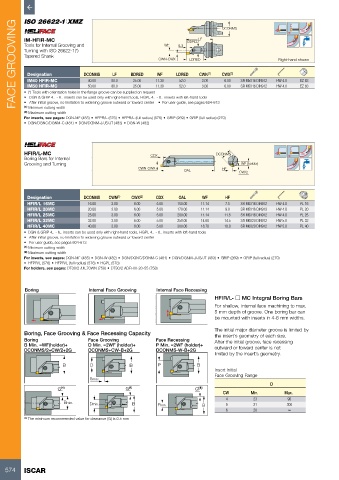
Boring Internal Face Grooving Internal Face Recessing
HFIR/L- o MC Integral Boring Bars
For shallow, internal face machining to max.
5 mm depth of groove. One boring bar can
be mounted with inserts in 4-6 mm widths.
The initial major diameter groove is limited by
Boring, Face Grooving & Face Recessing Capacity the insert’s geometry of each size.
Boring Face Grooving Face Recessing After the initial groove, face recessing
B Min. =WF(holder)+ D Min. =2WF (holder)+ P Min. =2WF (holder)+ outward or toward center is not
DCONMS/2+CW/2+2G DCONMS+CW-B+2G DCONMS-W-B+2G
limited by the insert’s geometry.
B D B P B
Insert Initial
Face Grooving Range
5max
D
G (1) G (1) G (1)
CW Min. Max.
4 23 90
Bmin. Dmin. B Pmin. B 5 21 300
6 20 ∞
(1) The minimum recommended value for clearance (G) is 0.5 mm
574 ISCAR